Saturday, July 11, 2009

Big update

This is a big update to my graphic demo. I finished implementing a sun shader, which includes HDR, bloom, and God ray. Please follow this link to watch it in HD:

Sun Shader

I also finish implementing Depth of field (or DOF). Here is a picture:
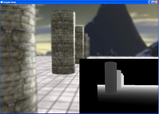

The lower right rectangle shows the depth test for the scene. I'll write about this two effects in details next blog. Take care for now.

Thursday, May 7, 2009

Dynamic cube mapping for real reflection / refraction

As mentioned in previous post, I was working on how to create a true reflection / refraction model. Initially I try to use dual-paraboloid mapping but I wasn't satisfying with the result. Then I decided to look into dynamic cube mapping and searched around the Internet for some hints.

To my disappointment, I didn't get many useful results. Luckily I found a DirectX sample called HDR Cube Mapping which implemented dynamic cube mapping, and it helped me a lot :D. So I decided to write this blog to show my take on dynamic cube mapping and also serve as a tutorial for who wants to achieve this technique.


What is a cube map?

So first let's look at what a cube map is. Here is the definition of a cube map from DirectX document (Click on the image to see larger version):


So after we get the definition of cube map down, let's talk about the use of cube map. You can use cube map to create skybox to envelope your game and create any atmospheric effects such as day / night time. One use of cube map is sample texture for any reflection / refraction object. However, one flaw of this technique is since the cube map is static, the reflection / refraction model won't reflect / refract any object that are not part of that cubemap.

To overcome this flaw, we will look into dynamic cube mapping. As the name suggest, a dynamic cube map is dynamic and store information of all objects in the scene. It changes as the objects in the scene change. To build a dynamic cube map, you will render the scene six times, each time into a face of the cube map. You can render images to the individual faces of the cube map just like you would any other texture or surface object.

The most important thing when render to a cube map face is setting the transformation view matrices so that the camera is positioned properly and points in the proper direction for that face: forward (+z), backward (-z), left (-x), right (+x), up (+y), and down (-y). Here is the setup code:


void RenderIntoCubeMaps()
{
// Save the camera position
float xSave = gCamera->position().x;
float ySave = gCamera->position().y;
float zSave = gCamera->position().z;

// Set it to the reflection/refraction object position
// Here I put it at the origin (0, 0, 0)
gCamera->position().x = 0.0f;
gCamera->position().y = 0.0f;
gCamera->position().z = 0.0f;

// Prepare the projection matrix
D3DXMATRIX mProj;
D3DXMatrixPerspectiveFovLH(&mProj, D3DX_PI * 0.5f, 1.0f, 1.0f, 10000.0f);


Notice here the angle of projection. Since we break the space around us into 6 faces, we will use a projection of 90 degrees or PI / 2 to cover each one.


// Store the current back buffer and z-buffer
LPDIRECT3DSURFACE9 pBackBuffer = NULL;
LPDIRECT3DSURFACE9 pZBuffer = NULL;
gd3dDevice->GetRenderTarget ( 0, &pBackBuffer );
if(SUCCEEDED( gd3dDevice->GetDepthStencilSurface( &pZBuffer ) ) )
gd3dDevice->SetDepthStencilSurface( g_pDepthCube );


Here we use a stencil buffer g_pDepthCube to help render into cube map faces. Move on to setup view matrix:


for(DWORD nFace = 0; nFace < 6; nFace++)
{
// Standard view that will be overridden below
D3DXVECTOR3 vEnvEyePt = D3DXVECTOR3(0.0f, 0.0f, 0.0f);
D3DXVECTOR3 vLookatPt, vUpVec;

switch(nFace)
{
case D3DCUBEMAP_FACE_POSITIVE_X:
vLookatPt = D3DXVECTOR3(1.0f, 0.0f, 0.0f);
vUpVec = D3DXVECTOR3(0.0f, 1.0f, 0.0f);
break;
case D3DCUBEMAP_FACE_NEGATIVE_X:
vLookatPt = D3DXVECTOR3(-1.0f, 0.0f, 0.0f);
vUpVec = D3DXVECTOR3( 0.0f, 1.0f, 0.0f);
break;
case D3DCUBEMAP_FACE_POSITIVE_Y:
vLookatPt = D3DXVECTOR3(0.0f, 1.0f, 0.0f);
vUpVec = D3DXVECTOR3(0.0f, 0.0f,-1.0f);
break;
case D3DCUBEMAP_FACE_NEGATIVE_Y:
vLookatPt = D3DXVECTOR3(0.0f,-1.0f, 0.0f);
vUpVec = D3DXVECTOR3(0.0f, 0.0f, 1.0f);
break;
case D3DCUBEMAP_FACE_POSITIVE_Z:
vLookatPt = D3DXVECTOR3( 0.0f, 0.0f, 1.0f);
vUpVec = D3DXVECTOR3( 0.0f, 1.0f, 0.0f);
break;
case D3DCUBEMAP_FACE_NEGATIVE_Z:
vLookatPt = D3DXVECTOR3(0.0f, 0.0f,-1.0f);
vUpVec = D3DXVECTOR3(0.0f, 1.0f, 0.0f);
break;
}

D3DXMATRIX mView;
D3DXMatrixLookAtLH( &mView, &vEnvEyePt, &vLookatPt, &vUpVec );


After the view and projection matrices have been set, we will render the scene into the cube map face. But to do so, we have to obtain a pointer that point to the surface of the cube map face and use it to render.


LPDIRECT3DSURFACE9 pSurf;
g_apCubeMap->GetCubeMapSurface((D3DCUBEMAP_FACES) nFace, 0, &pSurf));
gd3dDevice->SetRenderTarget (0, pSurf); // Set the render target.
ReleaseCOM( pSurf ); // Safely release the surface.

// Clear the z-buffer
gd3dDevice->Clear( 0L, NULL, D3DCLEAR_ZBUFFER, 0x000000ff, 1.0f, 0L) ;

gd3dDevice->BeginScene();

// render code here....

gd3dDevice->EndScene();

// We're done, so restore the camera position
gCamera->pos().x = xSave;
gCamera->pos().y = ySave;
gCamera->pos().z = zSave;

// Restore the depth-stencil buffer and render target
if( pZBuffer )
{
gd3dDevice->SetDepthStencilSurface( pZBuffer );
ReleaseCOM( pZBuffer );
}
gd3dDevice->SetRenderTarget( 0, pBackBuffer );
ReleaseCOM( pBackBuffer );
}


So that's the code for implementing dynamic cube mapping. Now let's look at the result, disadvantage and optimization.

Result:

Video: YouTube link.

Disadvantage:

* Since there are sixe cube map faces, we have to render the scene six times every time. This can significantly slow down the frame rate of the application/gamese.

Optimization:

* There are ways to ensure that we don't have to render the scene six times every time. For example, we don't have to render into the face that the camera can't see.

* Use other technique such as dual-paraboloid mapping to achieve the same effect ( You can look at the right for GraphicRunner blog, he has an excellent tutorial on that ). However, dynamic cube mapping gives the best result compare to other techniques ( that's what I think :D ).

That's it folks. Hope you guys find this post helpful. If you have any questions or suggestions please let me know. Next I will try to implement a sun shader and crepuscular ray ( or God Ray ). Until next time, take care.

Thursday, April 30, 2009

Parallax Occlusion Mapping and Glass HLSL

Ok so I just setup my blog here to post my process on my graphic demo. I doing this to improve my 3D graphic skill as well as work on my portfolio to find an internship.

Here is my current graphic demo. It's written using DirectX 9.0c and HLSL.

1) Overview: So in this demo I implement these graphic techniques:

* Cube mapping to create the sky box.

* Normal mapping for the floor and those columns.

* Reflection and refraction on water. I first build reflection and refraction maps, then project them onto the water plane. Then at each water plane pixel, I blend refraction and reflection associated texels together, along with material and lighting to produce the final pixel colors for the water.

All of these techniques I learned from Frank D. Luna's book called Introduction to 3D Game Programming with DirectX 9.0c A Shader Approach.

So the demo looks good but I still think it doesn't have enough cool techniques. So I implement another popular effect: the glass effect

2) Glass shader:

So voila, a glass teapot ! It has both reflection and refraction properties just like the water.The violet color is due to I try to implement some rainbow color as the result of refracted white light. So here is the process:

- For reflection: we look up the reflection vector and use it to sample from the environment map.

- For refraction: we'll use Snell's refraction law:

n1 * sin (theta1) = n2 * sin (theta2)

with theta1 is the incoming light angle and theta2 is the refracted angle. n1 and n2 are just refractive indices of two media. After compute the refraction vector, we also use it to sample from the environment map.

- Finall we combine reflection and refraction with some weight. Here is the HLSL code:


// Look up the reflection
float3 reflVec = reflect(-toEyeW, normalW);
float4 reflection = texCUBE(EnvMapS, reflVec.xyz);

// We'll use Snell's refraction law
float cosine = dot(toEyeW, normalW);
float sine = sqrt(1 - cosine * cosine);

float sine2 = saturate(gIndexOfRefractionRatio * sine);
float cosine2 = sqrt(1 - sine2 * sine2);

float3 x = -normalW;
float3 y = normalize(cross(cross(toEyeW, normalW), normalW));

// Refraction
float3 refrVec = x * cosine2 + y * sine2;
float4 refraction = texCUBE(EnvMapS, refrVec.xyz);

float4 rainbow = tex1D(RainbowS, pow(cosine, gRainbowSpread));

float4 rain = gRainbowScale * rainbow * gBaseColor;
float4 refl = gReflectionScale * reflection;
float4 refr = gRefractionScale * refraction * gBaseColor;

return sine * refl + (1 - sine2) * refr + sine2 * rain + gLight.ambient/10.0f;


The effect is based on ATI glass shader. The downside of this is the teapot just reflects and refracts the environment map only. So anything that is not of the environment ( water plane, columns, etc. ) will not be visible through the glass. I'm currently searching for a solution for this so if you know any please suggest :).

The latest technique that I implement is Parallax Occlusion Mapping ( or POM ).

3) Parallax Occlusion Mapping (POM):


POM is used to replace normal mapping technique in order to achieve many features such as:

- Display motion parallax

- Calculate occlusion and filters visibility samples for soft self-shadowing.

- Use flexible lighting model

This technique is explained in detail in Practical Parallax Occlusion Mapping for Highly Detailed Surface Rendering by Natalya Tatarchuk of ATI. I personally don't fully grab all the technical details yet so I'm still reading on it. The implementation is learned from the POM sample from DirectX :D. However, this is what I understand so far:

- First we encode surface displacement information into a scalar height map. This information often stored in the alpha channel of the normal map.

- Then effect of motion parallax for a surface can be computed by applying this height map and offsetting each pixel in the height map using geometry normal and the view vector.

So as you can see from the picture above, the view ray from the eye to the pixel on the polygonal surface represent what we would have see if we use normal mapping. However, in the actual geometry, we would have see the pixel correspond to t-off instead. So how do we fix that ?


- We have to compute the intersection point of the view ray and the height-field of the surface. We do this by approximate the height field (seen as the light green curve) as a piecewise linear curve (seen here as dark green curve), intersecting it withe the given ray (the view ray) for each linear section.

- We start by tracing from the input sample coordinates t-0 along the computed parallax offset vector P. We perform linear search for the intersection along the parallax offset vector. Each piecewise segment is of step size sigma. To test each segment, we simply use the height displacement value from each end point to see if they are above the current horizon level.

- Once the segment is found, we compute the intersection between it and the view ray. The intersection of the height field yields the point on the extruded surface that would be visible to the view. From this point, we can trace back to t-off and compute the offset vector for the texture.

Here is the video I made demonstrates POM technique:


Phew that's a lot of technical details. If you want a simpler explanation I suggest you read Jason Zink's A closer look at parallax occlusion mapping at GameDev.net. Here is the link :